TREASURE Technical Team | Corporate Technical Author — Battery Energy Storage and EV Charging Systems | Published August 3, 2026
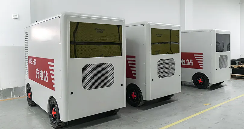
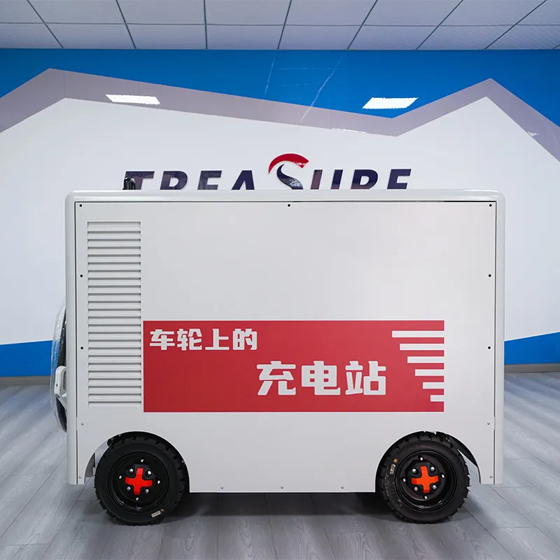
A mobile EV charging robot is a battery-integrated unit on a mobile chassis that drives or is towed to a parked vehicle and delivers DC power on demand. Capacity typically ranges 55–200 kWh, with charging power from 40–120 kW, removing the need to build a fixed charging bay at every parking stall.
What a Mobile Charging Robot Actually Does
Strip away the marketing language around autonomy and dispatch apps, and a mobile charging robot is three subsystems bolted together: a battery pack sized for one or more charging sessions, a DC output stage that talks to the vehicle’s charging protocol, and a mobile base that gets the unit from a storage dock to the parking spot. The battery charges from the grid during off-peak hours, then discharges into vehicles during the day — shifting when the site draws power rather than adding a new fixed load at peak times.
Most current buyer guides frame this category around self-navigating, app-dispatched consumer robots — units that summon themselves to a parking space via a phone app. That framing answers “how smart is it” rather than “how much can it deliver, at what voltage, to how many vehicles per day.” For a charging operator sizing a deployment, the second set of questions is the one that determines whether the unit fits the site.
Inside the Lineup: Capacity, Power, and Weight
TREASURE’s Mobile EV Charging Robot Series is published across four energy-capacity tiers, each with a corresponding charging-power option and approximate unit weight:
| Емкость энергии |
Charging Power Options |
Approx. Weight |
| 55 kWh |
40 kW, 60 kW, 80 kW, 120 kW |
~0.5 t |
| 100 kWh |
40 kW, 60 kW, 80 kW, 120 kW |
~0.9 t |
| 150 kWh |
40 kW, 60 kW, 80 kW, 120 kW |
~1.45 t |
| 200 kWh |
40 kW, 60 kW, 80 kW, 120 kW |
~1.9 t |
Battery and Voltage Architecture
The cell specification behind the series is 314 Ah, with the pack operating across a 525.6–700.8 V voltage window. That range matters more than the kWh number by itself: a higher operating voltage lets the same charging power move through lower current, which is part of why a 120 kW output is achievable from a chassis-mounted unit rather than a stationary cabinet. Buyers evaluating multiple mobile-charger vendors should ask for the operating voltage window specifically — output kW alone doesn’t tell you how the pack gets there.
Connectors, Controls, and Deployment Configuration
Each unit in the series integrates:
- A BMS managing the 314 Ah cell bank across its voltage range
- CCS and GB/T connector support, with additional interfaces available per project
- An onboard HMI for local operation
- Overcharge and short-circuit protection built into the safety layer
- Optional remote monitoring for fleet-level visibility
- OEM/ODM configuration for branding and interface customization
Compared to the autonomous, app-dispatch consumer designs that dominate current mobile-charger coverage, this configuration is built around operator-managed deployment — a person or dispatch system moves the unit and initiates a session — rather than the robot self-navigating to the vehicle. For a fleet or site operator running scheduled charging windows, that’s a meaningfully different operating model than the walk-up consumer use case, and it changes what staffing and site-layout planning actually looks like.
Where Mobile Robots Make Sense — and Where They Don’t
Fixed DC charging infrastructure runs into three recurring constraints: available electrical capacity, civil-works time for trenching and foundation work, and physical space for permanent bays. Mobile charging robots address the first two directly, since the battery buffers grid draw and there’s no excavation required. They don’t solve a genuine grid-capacity shortfall at a site with no spare load headroom at all — the robot still needs to recharge from somewhere, and if the site’s total available power is the constraint, a battery-buffered charger just shifts the timing problem rather than removing it.
A common buyer mistake is treating higher energy capacity as a straightforward upgrade path. A 200 kWh unit at roughly 1.9 t needs a mobile base, ramp access, or lift capacity that a 55 kWh, 0.5 t unit doesn’t. Site layout and floor-loading constraints should be checked against the weight column before capacity, not after.
Comparing the Format: Mobile Robot vs. Fixed DC Charger
| Factor |
Мобильный зарядный робот |
Fixed DC Fast Charger |
| Civil works |
Minimal — no foundation/trenching |
Required — foundation, conduit, often panel upgrade |
| Deployment speed |
Days to weeks |
Weeks to months |
| Site flexibility |
Repositionable across a lot or site |
Fixed to installed location |
| Continuous power draw |
Buffered by onboard battery |
Draws from grid at time of use |
| Energy ceiling per session |
Capped by onboard capacity (55–200 kWh) |
Limited mainly by grid connection |
Neither format replaces the other outright; sites with high, predictable daily throughput generally still need fixed infrastructure, while mobile units fit overflow demand, temporary sites, and locations where a permanent bay isn’t yet justified.
Pricing and Getting a Quote
Pricing for the Mobile EV Charging Robot Series is not publicly disclosed and is determined project by project, based on selected energy capacity, charging power, voltage architecture, connector standard, battery configuration, BMS/EMS requirements, communication protocol, OEM/ODM branding requirements, and delivery terms. To get an accurate quote, be ready to share your application scenario, required power and energy capacity, EV fleet profile, on-site grid conditions, and project timeline.
ЧАСТО ЗАДАВАЕМЫЕ ВОПРОСЫ
Q: What’s the difference between a mobile EV charging robot and a charging trailer or van?
A: Both are battery-buffered mobile chargers, but a robot in this category is built around a compact mobile chassis (0.5–1.9 t in this lineup) intended for repositioning within a site, rather than the higher-capacity, road-towed format typical of a charging van or trailer.
Q: Can one unit charge more than one vehicle?
A: The published specifications describe a single onboard battery and DC output stage per unit; simultaneous multi-vehicle charging isn’t part of the disclosed configuration for this series and should be confirmed directly if it’s a requirement.
Q: Does higher charging power always mean faster charging?
A: Only up to the limit of what the vehicle’s onboard charger accepts. A 120 kW unit doesn’t deliver 120 kW into a vehicle rated for 60 kW peak DC input — actual session time depends on the vehicle’s own charging curve as well as the robot’s rated output.
Q: What connector standards does the series support?
A: CCS and GB/T are listed, with additional interfaces available on a project-configured basis. Confirm the exact connector and communication protocol (e.g., OCPP version) for your specific fleet before ordering.

 Мобильные роботы для зарядки электромобилей
 Автомобильный источник аварийного питания
 Системы хранения энергии
 Каталог зарядных устройств постоянного тока для EV
 Зарядное оборудование постоянного тока V2V